by Dennis Bemmann
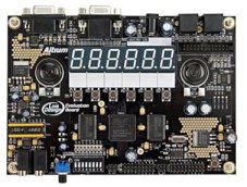
Altium Ltd. offers a pretty cool FPGA development board, the LiveDesign Evaluation Board EB1. This board has a rich feature set including many switches and LEDs, fast RAM, a 6 digit 7-segment display, connectors for VGA, RS232 and PS/2 and a delta-sigma DAC audio chain with two speakers. The board is available either with a Xilinx Spartan-3 400 chip, or with a similar Altera device. This page is about the Xilinx version.
The price of the board (99$) is unbeatable - this makes it interesting to hobbyists. The board comes with a 30-day evaluation license for Altium's PCB/FPGA design software. The software is really great, but poor students like me cannot afford it, that's why I was trying to find out how the board can be used with the free ISE WebPack software from Xilinx. The documentation of course doesn't say anything about it.
First observation: the board can be configured with iMPACT. You don't even need a separate download cable, just plug the parallel cable that comes with the board into the LPT port and the board will emulate a Xilinx cable. iMPACT detects the FPGA in boundary-scan mode. Assign a bitstream, download and there you go.
Well... there is no UCF file provided with the board, because Altium's vendor-independent software has its own concept for constraints and configuration. That means, you have to manually find the FPGA pins in the board's schematic and write your own UCF file. Looking up pins in schematic sheets is very boring. No fun, so I did it for you. Download my sample UCF file or my complete UCF file.
# --- PAD LOCATIONS LISTED ---
# clk             - Clock 50 MHz
# testsw          - Test/Reset button
# audio<1:0>      - Audio outputs 0=left 1=right
# leds<7:0>       - LEDs (bottom left on board)
# switches<7:0>   - Dip switches
# buttons<5:0>    - Buttons below the 7-segment displays
# dign<7:0>       - 7-segment displays, n = number of digit [0,1,2,3,4,5]
# vga_c<2:0>      - VGA color pins, c = [r,g,b]
# vga_hsyn        - VGA horizontal sync
# vga_hsyn        - VGA vertical sync
# rs232_cts       - RS232 clear to send
# rs232_rts       - RS232 ready to send
# rs232_rx        - RS232 receive
# rs232_tx        - RS232 transmit
# ps2a_data       - PS/2 port A
# --- TO DO ---
# more PS/2 connectors, SRAM, Expansion pins
To get going, start a new ISE project and select the correct FPGA type (Spartan-3 XC3S400-FG456). I have prepared sample code to demonstrate the board's components. Download my sample VHDL file. Put it into your ISE project and implement it on the board using my UCF file from above. You can then turn on and off the LED bar using the DIP switches, and the 7-segment display shows a counter counting binary. Looks weird but works. Press the user buttons to turn on some segments of the second digit and to hear a few sounds. They sound like a telephone ringing.
This should get you started. If you have something new for the board, please let me know. I'd be interested in a memory controller, and even more in peripherals that use the expansion pins...
Dennis Bemmann